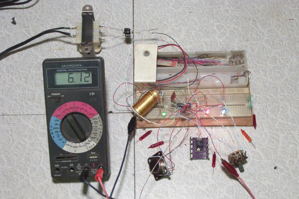
Breadboard version of tester. This looks like something out of Thomas Edison's laboratory, but it works. The multimeter shows supply A set for 6 volts output.
Miniature light bulb tester/evaluator.
Finally the long awaited plans for a miniature bulb tester!
Here is a project that's perfect for anyone who restores light sets - a light bulb tester designed to test and identify the miniature bulbs used on series wired Christmas light sets. It has two D.C. power supplies designed for this purpose. Supply A, based on the LM723 analog voltage regulator, is selectable to 2.5, 3.5, and 6.0 volts. Supply B, which uses the LM317 analog regulator, is continuously variable from 1.2 to 13 volts, which includes just about every bulb voltage used. This tester also has a meter to measure the current draw of a bulb, which is very important with series wired sets.
 |
Breadboard version of tester. This looks like something out of Thomas Edison's laboratory, but it works. The multimeter shows supply A set for 6 volts output. |
Circuit description and operation.
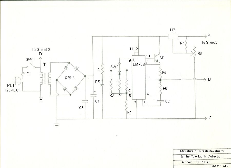
110 volts A.C. goes to fuse F1, then SPST switch SW1, and is input to
transformer T1. T1 steps the voltage down to 12 volts A.C. Bridge rectifier
module CR1 converts the A.C. to D.C. which is filtered by C1. R9 and
LED pilot light DS1 show power on status and also serve to drain the charge on
C1 when power is turned off.
Supply B uses U1, an LM723 analog voltage regulator. SW2, R1,R2,R3 and R4 set
U1 to output 2.5, 3.5, and 6.0 volts. Q1 is an NPN current boosting
transistor configured in emitter follower mode. R5 sets the supply to current limit to 0.5
amps, enough to test most mini bulbs. Current limiting is important because if
the bulb you are testing is burned out, then it's shunt will likely be tripped,
and when that happens the bulb becomes a dead short.
Supply A uses U2, an LM317T adjustable regulator which needs only R6 and potentiometer R7
to complete the circuit. U2 is current limited to 1.5 amps by design.
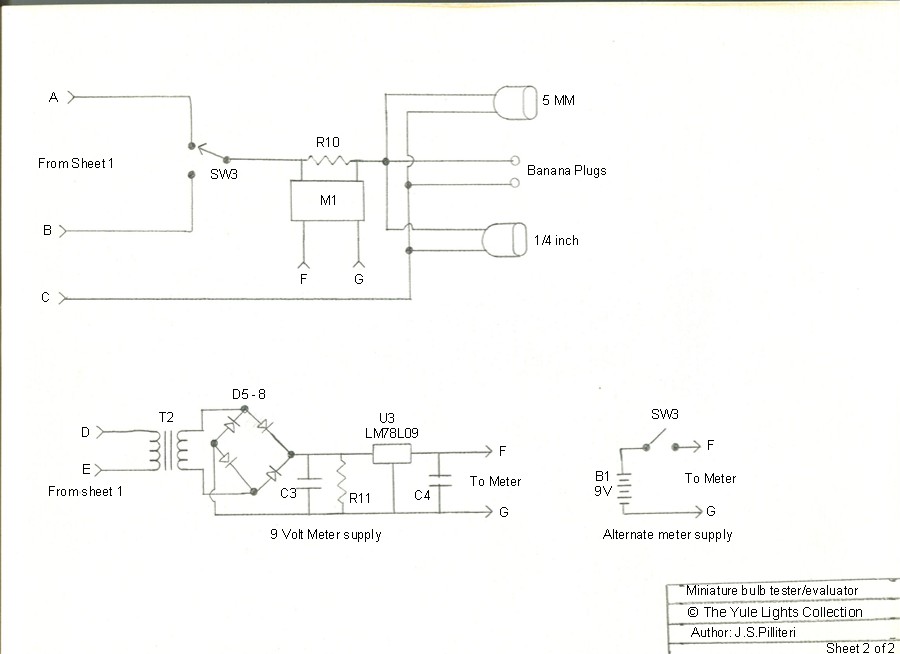
Meter M1 is a 0 to 200 millivolt digital panel meter. Current sense resistor R10
scales the meter to read 0 to 2 amps. The meter is placed after an SPDT center
off switch, so it will read current from supply A or B.
T2, D5 - 8, U3, R11, C3 and C4 form a low ripple 9 volt supply to power the
digital panel meter. If you want to simplify things, you can power the meter
with a 9 volt transistor battery and switch. Note that the 9 volt supply for the
meter must be a "floating" supply isolated from the lamp test supply. IE: no
common ground!
Note: 2 separate transformers are used only because it was not possible to find
a transformer with 2 secondaries.
Schematic Diagram of tester.

Page 1

Page 2
Parts list for Miniature Bulb tester. Three sources are listed
with links to their home pages at the top.
Parts with an asterisk* are critical values and should not be substituted.
| Part reference | Part type | NTE Electronics | Radio Shack | Jameco Electronics |
| U1 | LM723 regulator | NTE923D | 24467 | |
| U2 | LM317T regulator | NTE956 | 276-1778 | 23579 |
| U3 | LM78L09 regulator | NTE1902 | ||
| Q1 | TIP29 transistor | NTE291 | ||
| R1* | 8.2 K resistor | QW282BR | ||
| R2*, R4* | 4.7 K resistor | QW1475BR | ||
| R3* | 820 ohm resistor | QW0825BR | ||
| R5* | 1.0 ohm resistor, 1/2 W | HW1D0 | ||
| R6 | 2.0 K resistor | QW220BR | ||
| R7* | 1.0 K resistor | QW210BR | ||
| R8* | 10 K ohm pot | 271-1715 | ||
| R9 | 750 ohm resistor | QW0750BR | ||
| R10* | 0.1 ohm resistor, 1/2 W | HWD10 | ||
| R11 | 470K ohm 1/4 watt | QWCC447 | ||
| CR1- CR4 | Bridge Rectifier | 276-1146 | 178183 | |
| CR5 - CR8 | Bridge Rectifier | 276-268 | 102980 | |
| C1 | 2200 uF 35 V capacitor | NEH2200M35 | 272-1020 | |
| C2 | 100 pF capacitor | 89110 | 272-123 | |
| C3 | 220 uF 35 V capacitor | NEV220M35 | ||
| C4 | 4.7 uf 16V capacitor | TD4.7M16 | ||
| T1 | 12V,1.2A transformer | 273-1352 | ||
| T2 | 12.6V 300ma transformer | 273-1385 | ||
| SW1 | SPST Toggle switch | |||
| SW2 | Rotary switch 3 position | G3SR024-R | ||
| SW3 | SPDT center off switch | 21910 | ||
| M1 | 3.5 digit panel meter | 175951 | ||
| DS1 | Green LED | 30038 | ||
| Project box | 7x5x3 | 270-1807 | ||
| F1 | Fuse, 1/2 amp | 270-1003 (4 pack) | ||
| Fuse holder | Block type | 270-739 | ||
| Fuse holder (alt) | Panel type | 270-367 | ||
Construction - The circuitry is mounted
on perforated board typically used for prototyping. Q1 and U2 are mounted on a
heat sink and also must be insulated from each other. As you can see in the
photo below, the transformers, circuit board and heat sink are in the bottom of
the box, while the meter, switches, indicator light and test connectors are
mounted on the cover.
Note: the only reason 2 separate transformers are used is because it was not
possible to find a transformer with 2 secondaries.
Tester shown with cover removed. Click photo to see larger view.
Operation - To test a bulb, first
install it into the appropriate socket depending on base size it will be 1/4
inch or 5 millimeter. Use the binding posts if a bulb just has bare wires. It
may be necessary to scrape the oxide from the wires to insure good contact.
Now adjust the output voltage to the lowest setting and turn on the output. The
bulb should light up and the current meter will show a current draw. Now
increase the voltage until the light output looks right. Watch the base area
where there is no paint coating. Look for the light to turn yellow to
white at that point you will have the correct voltage rating for the bulb. Now
observe the current. You now know the bulbs voltage and current rating.
If the bulb is burned out, there are two possibilities. If the filament and
shunt are open there will be no current draw. Make sure you have good contact in
the socket if you see no current.
The second possibility is for the shunt to be activated. Then there will be a
high current draw because the shunt is a short circuit across the bulb.
Footnotes - These plans are considered copyrighted
material. You may: Print the plans and use them to construct the tester for your
own use, or link to this page from another website.
You may not: Post photos from this page to other photo sharing websites, or sell
the plans.